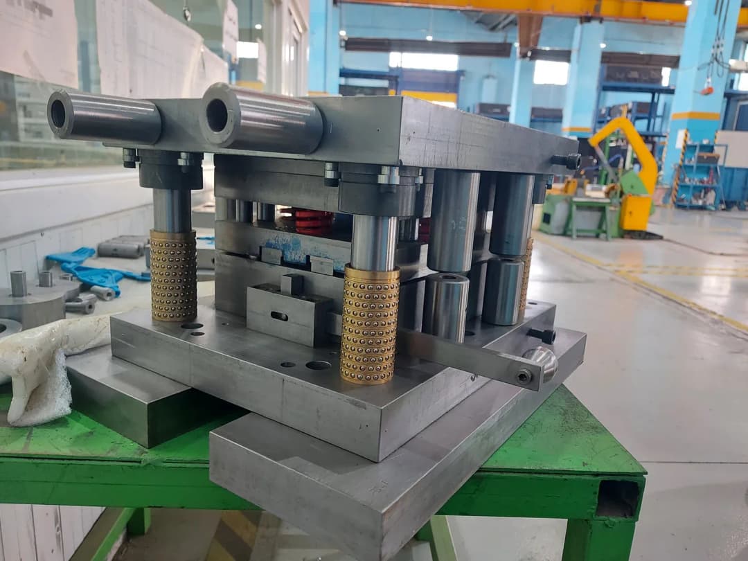
ZINITEK designed and machined a custom Gasket Nut stamping die set. The CAD model and the photos of the actual die below show the same die set, so you can review its construction before discussing a solution for your own product.
Scope of work: die design and machining
For the Gasket Nut die set, ZINITEK handled both design and machining. This project page presents the overall model and photos of the actual die set; the related technical article goes further into the strip layout and each die assembly.
Die construction for the Gasket Nut part
The Gasket Nut CAD model shows the upper die assembly, the lower die assembly, the guiding system and the strip layout. The different views help customers visualize the die construction and discuss the approach before the design is finalized.
For a custom part, the product geometry, material, thickness and the dimensions to be controlled are the input data. How the die mounts on the press and how the stock is fed also need to be clarified so that the design fits the customer's production line.
Design already available: agree on the machining scope
If you already have 2D drawings or a 3D design package, you can send the data so ZINITEK can check the information needed for a quote. The scope may be machining die components, or building and assembling the complete die set as agreed.
Please also provide material, heat treatment, tolerance and critical surface requirements if these have already been defined. For assembly design files, include the linked part files so the data can be checked in full.
No design yet: start from your requirements or a product sample
When you only have a physical sample, photos or a product concept, the first step is to clarify the part's function, critical dimensions and production conditions. From there, both sides agree on the work to be done before the die is machined.
You can start with native CAD data from Inventor, SOLIDWORKS or NX; exchange formats such as STEP, IGES or Parasolid; 3D scan data; or a physical sample. Whether a file can be read depends on its format and software version. Receiving samples, measurement or geometry reconstruction is discussed case by case.
Information that helps define the approach and the quote
- Drawing, CAD file or photos of the part to be stamped.
- Stock material and thickness.
- Dimensions, tolerances, burr and surface requirements.
- Expected production volume and details of the press currently in use.
- Desired scope: design, component machining, complete die build or improvement of an existing die.
If you need to improve a die that is already in use, add photos of the defective parts and describe the step where the problem occurs. This data helps us discuss the right requirements and avoid quoting on an unclear scope.
Discuss a die set for your product
Send a drawing or reference sample along with your technical requirements so ZINITEK can discuss the design and machining approach. Every die set is assessed against the part to be produced and the customer's operating conditions.
Send a die design or machining request
View our mold and die design and manufacturing service
Learn about the Gasket Nut die construction and the data to prepare
Project Gallery